
Setup of inductive loops#
Guidelines for how to program, setup, integrate and log instruments along an inductive line.
Terminal#
Software like TeraTerm or Putty were used successfully for communication.
TeraTerm (Windows)#
File>New connection...>Serialwith correct COM portSetup>Serial port...>Speed:
115200(SIMC) or19200(UM) or whatever the device is set toFlow control:
noneorXon/Xoff(when sending files via terminal)Transmit delay:
5or10msec/line when sending files via terminal
File>Log...to activate logging of terminal output
Putty (Linux)#
Serial line:
/dev/ttyUSB0(when USB to serial adapter was used)Speed:
115200Logging activated
Terminal > Check
Implicit CR in every LF
General procedure#
Tip
Always activate logging of terminal output into a .txt file or similar for later troubleshooting
Collect instruments according to mooring plan drawing/table
Put every instrument once alone on the test inductive line that has a SIMC/modem on it
Check that IDs are correct
Sound9 sensors (CTD, T, etc.) are usually contacted via a group command
xt2(group 0) orxt3(group 1)Other instruments are either connected via an Ultimodem (
mod 4andtelmode 3) or for instance Seabird IMs (mod 1andtelmode 1)to find the ID of connected modems either use last 2 digits of serial number or
fclorswtand receive ID viaid?
Make a test via interactive communication (see # Instrument communication) to all sensors and get the sensor info. Use the X-sensors syntax to communicate directly to X-sensors and connect to other instruments via their modems.
Put all sensors on the loop and create a test
a-fileand check that all sensors permodanswer. Some Sound9 IDs don’t work together, then a different ID has to be used, either by changing the ID or using another sensor (see # ID rules).
Instrument communication#
Interactive#
S9>eecchhoo ooffff \\ in case of double echo S9>getcd \\ display configuration of SIMC S9>getsd \\ display status data of SIMC S9>open im \\ opens in default baud rate 19200 (open im xxxxx for another baud rate) S9>MLN \\ measure line noise \\ X-sensors S9>mod 4 S9>telmode 3 S9>#X0iicd \\ display configuration of X-sensor with ID X0ii S9>xt2 n \\ sample all x-sensors up to `n` replies \\ Ultimodems with external sensors S9>fcl \\ capture line to talk to modem S9>id? \\ read IDs of connected modems S9>!iiGETCD \\ ii=last to digits of modem serial number S9>!iiIMFLAG=1 \\ power up sensor via serial connector S9>#iiSAMPLE-COMMAND \\ read sensor data S9>!iiIMFLAG=0 \\ power down sensor via serial connector S9>rel \\ release line \\ confirm that IMFLAG=0/1 powers up and down by measuring it \\ Seabird S9>mod 1 S9>telmode 1 S9>swt \\ send wake up tone S9>ID? \\ get IDs of connected instruments S9>!iiGETCD \\ ii=last to digits of serial number (! to logger) S9>#iiGETCD \\ ii=last to digits of serial number (# to sensor) S9>#iiDS \\ display status (Seabird commands) S9>#iiSL \\ read "sample last" \\ all Seabird commands are valid like STARTLATER, STARTNOW, etc.to disable im pass through mode
Script (a-file)#
Scripts are used for automation and data logging.
Start writing the file on to the logger via write a, lines with / or ;; are comments.
A commented template a-file can be found in this repo as well as a more extended version that was used latest (TT2025).
In TeraTerm the a-file can also be sent to the logger via the terminal.
Create the a-file in a
.txtfile in the following shapewrite a CONTENT OF a-FILE end a
Make sure the terminal is setup correctly with
Xon/Xofflike described above (# Terminal)File>Send file...> select the.txtfile created in step 1
The only way to add an a-file to a SIMC or UM is by connecting via RS232. It is not possible to write a while being connected through the inductive line to the modem.
SIMC data storage procedure#
The
S-fileis a RAM buffer. It records data from the host instrument during the script. Scripts can useCLEARBUFFERto empty this file andSAVE Dto save the current contents to the D buffer before clearing the file. The maximum length of theS-fileis6kB. If the host instrument sends more than6kBthen the script can use multipleSAVE Dcommands with an appropriate time delay in between.The
D-fileis a circular buffer with maximum length5 Mbytes(5242880 bytes)The
READ Dcommand reads the entire D file. TheREAD DLcommand reads only the last entry in the D fileSAVE Dmoves data from theS-fileto theD-file(leaving theS-fileempty).It is appropriate to use the
SAVE Dcommand multiple times in a single script. This results in multiple tags but under the same sample number. TheREAD DLcommand will return all data saved within the script even with multipleSAVE Dcommands in the program.
Deployment and logging#
Tip
During all deployment commands make sure to LOG the terminal for later troubleshooting.
Preparation checklist#
[ ] Measure SIMC and UM batteries and/or replace for new ones
[ ] The UM of the SIMC should not wake by noise of the line. Therefore
open imcheck that
WAKEUPSRC=1(only RS232) withgetcd
[ ] All UMs connected to instruments via RS232 should only respond to signals from the IM line. Therefore those should be set to
WAKEUPSRC=2(only IM). OBS In case an a-file is required on the UM make sure to first add it via connecting throughRS232before changing this setting.[ ] Set both master and all slave modems to
mod=4to use4800 baud@192.k (4)baud IM communications. This mode is not compatible with modems from Sea-Bird Electronics. Usemod=1on all modems for1200 baud@4.8k (1)baud IM communications.
Deployment#
After a script (a-file) has been placed on the SIMC it can be used for interactive and automated communication to all instruments on the line and for logging.
To test an a-file it can be
run aonce and data is displayed viaread dlFor logging the
period=n(nin minutes) is set for the desired interval when to cycle through the scriptCheck clock of system with
getsdand update time to UTC if necessary withtime yyyy-mm-ddTHH:MM:SSIf not already done during preparation: While terminal logging is on run a
!iigetcdor for XT sensors#X0iicd(ii=ID) on all instruments to log coefficients and settingsstartto activate logging
Commands#
Command |
Description |
|---|---|
|
display configuration settings |
|
display status data |
|
display event counters |
|
display hardware and firmware version ( |
|
|
|
reads |
|
terminates active mode |
|
get device ID of modem |
|
display configuration settings of |
|
send IM command through a remote modem to serial port, e.g. |
|
send IM command to a remote modem, e.g. |
|
activate IM with optional baud rate e.g. |
|
Captures IM network, starts transmitting a carrier signal on the IM network. Required prior to transmitting commands to the IM network |
|
send wake-up tone |
|
measure line noise |
|
singe sample and retrieve data from all XTP sensors. |
|
single sample and retrieve data from all 2 XT sensors. |
|
release IM line (opposite of |
|
turns double letters off when IM is active |
CEXIT N#
<Sample d='SIMC' mid='04HR' p='A' T='2000-01-01T00:12:00' c='1' v='1'>
the c='1' means the count is 1.
When a CEXIT happens it is marked in the sample like this:
<CEXIT c='6'/>
count = number of samples since last reset or last time the sample program
ended normally (end of file, not terminated by a CEXIT command)
count starts at 1 and is reset to 1 if it reaches 256
CEXIT N will immediately end the sample program (closing all ports) if (count % N)!=0
That means CEXIT 6 will for instance exit early for the first five samples, then not exit on the sixth sample.
It also means multiple CEXIT commands can be used in one file – though that requires careful attention to understand the sample timing.
Example#
Simple file with two CEXIT commands in it:
adclog
cexit 2
irhlog
cexit 4
eclog
There are three possible outcomes:
count = 1 or 3abort at line 2count = 2abort at line 4count = 4no abort, file runs to the end and count resets (will start at 1 on next run)
SIMC data retrieval#
Log terminal output for later troubleshooting or missing data
GETCDfor logging serial number and device infoGETSDto check for any unsaved bytes and get logger timenote down
timeof logger and compare to realUTCIf there is a
***WARNING: XXXX DATA BYTES NOT SAVED TO CARD!***run aSAVE Dto transfer data from flash memory to SD card. RunGETSDagain after to check the command worked as intended
READ Sto check that no remaining data is left temporaryGETECfor event count(optional)
READ Dand/orDUMPFLASHand/orREAD SDD, however, those commands might take quite a while depending on the amount of data recorded. The logger will need enough remaining power as well to transmit all the data to the terminal.SLEEPand disconnect the SIMC. Open the body of the SIMC with the screw plate or with the help of a vice.Press the small black button next to the SD and wait until the LED switches from blinking yellow to blinking green
Eject SD card and copy all of its content to a computer. There are usually two files with the name
S9 ###.TXTandS9 ###S.TXT(###=3 last digits of SN) where the first is the data file and the second the status log.
Integration of sensors in inductive loops#
TELMODE#
From UM manual R010Q
Note
The TELMODE setting in the receiving and transmitting modems must match for proper communication.
TELMODE 3 is required for binary data when the remote modem is an Ultimodem from S9. TELMODE 1 or 2 is required when the remote modem is an IM from SEA-Bird Electronics, depending on the IM’s BINARY setting. TELMODE 1 is required when the remote modem is a IM from Sea-Bird Electronics.
Soundnine instrument ID assigment#
Warning
Usually not for end-user-use, but we may need this.
The XT sensors don’t respond to normal IM commands like #ii or !ii. They use serial number addressing only.
Note
The modem needs to be mod 4, telmode 3.
The sensors respond to XT2 or XT3 depending on configuration. default is XT2 command.
Use
#X0iisg 1(sg=set group) to set serial numberX0iito group 1, which is read with theXT3command.Use
#X0iisg 0to set it back to group 0, which is read with theXT2command (default).
Hint
These commands are slow and not intended for use while deployed.
Use #X0iicd to read the configuration of the sensor, including the group assignment.
Warning
Make sure no other sensors are near the inductive loop when changing IDs, in case they accidentally pick up the signal!
#X0iiID 1changes the id number to 1.
Hint
This must be done carefully to prevent using two sensors with the same ID. The BAS ice shelf logger only uses hex-based IDs; experience is that this might give a better sensor separation.
ID rules with S Format#
Tip
ID should not be higher than 20 if there are no sensors with lower IDs on the line as then
XT2command times out before getting to IDs over 20CTDandCTDOusing theS7DandS7Fformat must skip next ID number. So if aCTDusesID 3thenID 4can’t be used by any sensor. (Reason: Some S data formats require more time to transmit than a single ID time slow allows.)XTandXTPsensors can use consecutive ID’s.S9 recommends using putting all
XTandXTPfirst starting atID 1, thenCTDandCTDOusing only odd or even ID’s, followed by fluorometers (XFL).XTandXTPsensors have a minimumID of 1.CTDhave a minimumID of 2.CTDOhave a minimumID of 3.XFLfluorometers (Chelsea Trilux) have a minimumID of 14.
Experiences that worked (before the above rules were known)#
XT ID 1 combined with 3 & 5 or 3 & 7 or 5 & 7 gives a repeated reply from ID 1
XT ID 3, 5 and 7 gives single replies and worked in combination CTD 12, 14 and 16
XT ID 2, 3, 4, 5, 9 and 10 with CTD 12, 14 and 16 also worked fine adding XT ID 8, 6 or 1 gave double replies or missing data from the CTDs.
All deployments from 2022/23
ISA500 altimeter:#
For integrating the ISA500 with the Soundnine Ultimodem (UM), two steps are required:
Telling the UM to provide power to the sensor (
IMFLAG=1).Reading the data from it using
a self defined sampling command e.g.
get_sampleorget_alti/get_ahrs(see pictures below)an a-file on the UM that listens to the ISA500 pinging, saves on a local
D-file(on the UM) and a transfer of theD-fileto a SIMC
Setting up ISA500#
Requirements
External power for setting up with software:
10 V,1 ARS232-MCIL8Fcable with external power connectionSeaViewsoftware
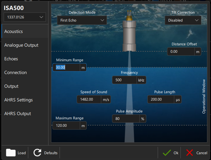
Acoustics#
Depending on setup, with a 60 m deployment minimum range = 30 m and maximum range = 120 m can be a good margin
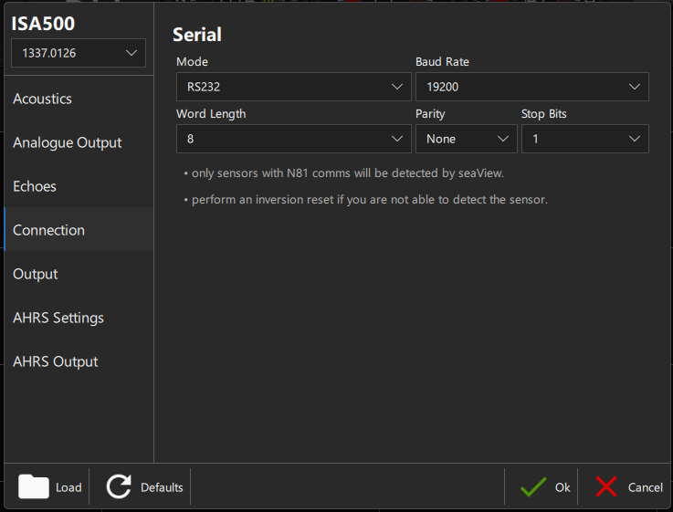
Connection#
Baud rate depending on what UM is using on the serial port (has to be the same). Default is 19200.
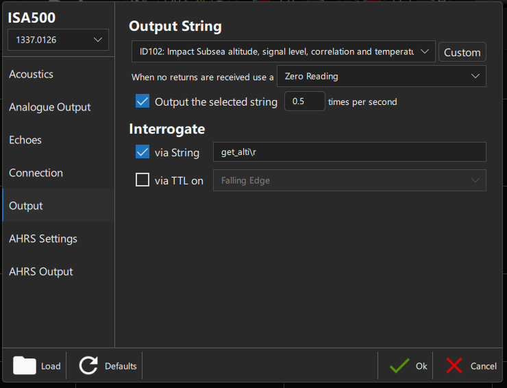
Output#
Based on what BAS used, format = ID102 is recommended. If the UM shall log the output for a defined time then the first option needs to be selected with the desired output frequency, e.g. 0.5 Hz. The interrogation string can always be defined and enabled, e.g. get_alti\r - meaning that sending the string get_alti followed by a carriage return (\r) to the ISA500 via the serial connection will trigger the ISA500 returning with one sample string.
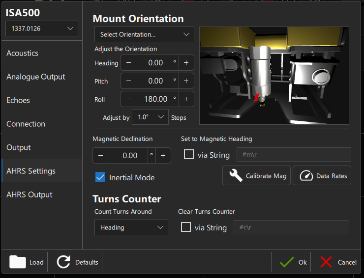
AHRS Settings#
If the sensor is mounted upward facing then Roll = 180° is required. All settings in this window should in theory be possible to account for in post-processing as well.
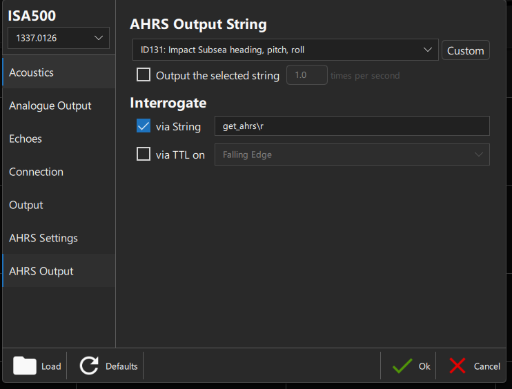
AHRS Output#
According to BAS recommendation format = ID131. In case the string is supposed to be logged with a specific frequency like the altimeter output above then the first option needs to be checked with the desired frequency. Otherwise, leave this option unchecked to save power. In the example below the ISA500 only sends an AHRS sample via serial once it gets triggered by e.g. get_ahrs followed by a carriage return (\r).
SIMC/UM setup#
Interrogate/Request single sample via get_alti/get_ahrs#
In this case a SIMC would send a command to the UM to request one sample from the ISA500 connected via serial to the UM. Check the interrogate example a-file in the repo.
Record frequent ISA500 burst pinging#
In this scenario the goal is to trigger a burst sampling of the ISA500. For this an a-file is placed on the UM that gets triggered by the SIMC and stores the data locally on the UM before being transferred to the SIMC.
The SIMC a-file is used to
switch on the power for the ISA500 from the UM using
imflagrun the
a-fileon the UM, every run of the UMa-filecreates a separate sample in the UMD-fileswitch off the power again
read the sample from the UM
D-file, needsSAVE IMevery 3.5s (conservative) inMOD 4with up to 480 bytes/s and 2 kB max buffer (S-file). The amount ofdelay&save IMrepetitions depends on the transferred file size of the most recent sample on the UM (DL=last sample on UM D-file).
the a-file on the UM
opens the serial port
all output is saved in the
S-file(max. 6 kB) on the UM and transferred to the UMD-file(max. 6 MB) by theSAVE Dcommand. The command needs to be timed so that the S-file doesn’t reach 6 kB.is used to trigger the interrogate string. This way altimeter data can be recorded as frequent pings while the AHRS data only gets requested a few times.
closes the serial port again
Power consumption#
For an interactive calculation of power consumption and resulting sampling plan check the ISA power sheet.