Technical instructions for inductive loops#
Below a guideline of how to assemble the inductive loops from a technical point of view. For a general wiring summary check the wiring.xlsx sheets.
Inductive test loop#
Tip
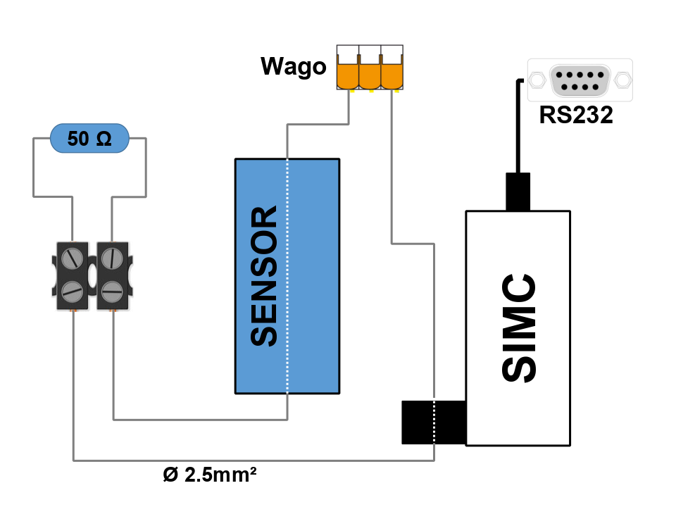
To test and communicate with the instruments a simple test loop is sufficient. For that a normal wire can be used (e.g. 2.5 mm²) like in the set up in the drawing below. The Wago clamp allows for easy replacement of sensors and the wire thickness allows for a quick push through the sensors instead of unscrewing sensors every time.
RS232#
Terminating inductive wire#
Caution
In general, it is important not to damage the mantle of the wire as this could shorten the inductive loop at the broken place and stop some instruments from making contact with the SIMC logger.
Only the ends of the cable should have a clear contact with the water.
Hint
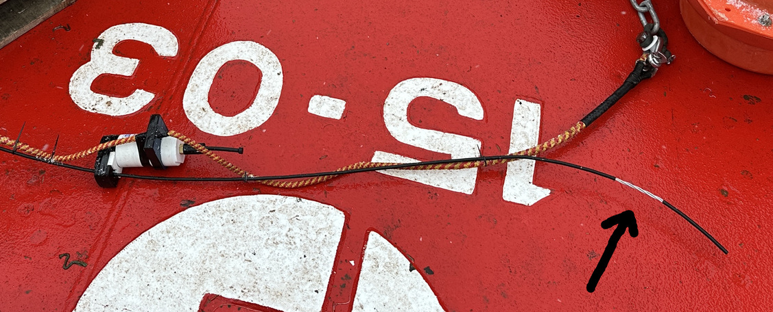
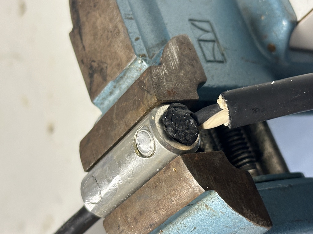
When terminating the wire with use of «kause» and wirelocks it is important to check that the cable mantle is not cut, otherwise, the inductive loop might be broken at this point. To check for a potential break measure with a multimeter between the wirelock and the end of the wire. There should be no connection.
Tip
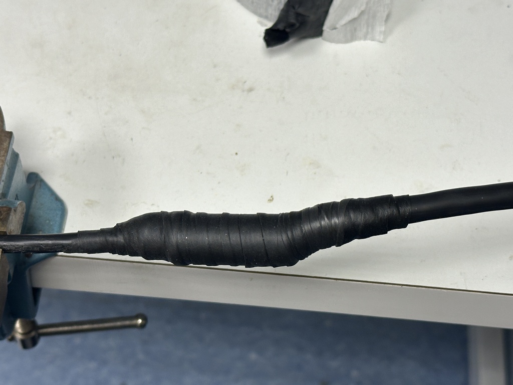
To support the wire mantle it is possible to first add some vulc/splicing tape on it before attaching the wirelock. After checking there is no shortcut, add additional round of vulc/splicing tape and electrical tape on the outside.
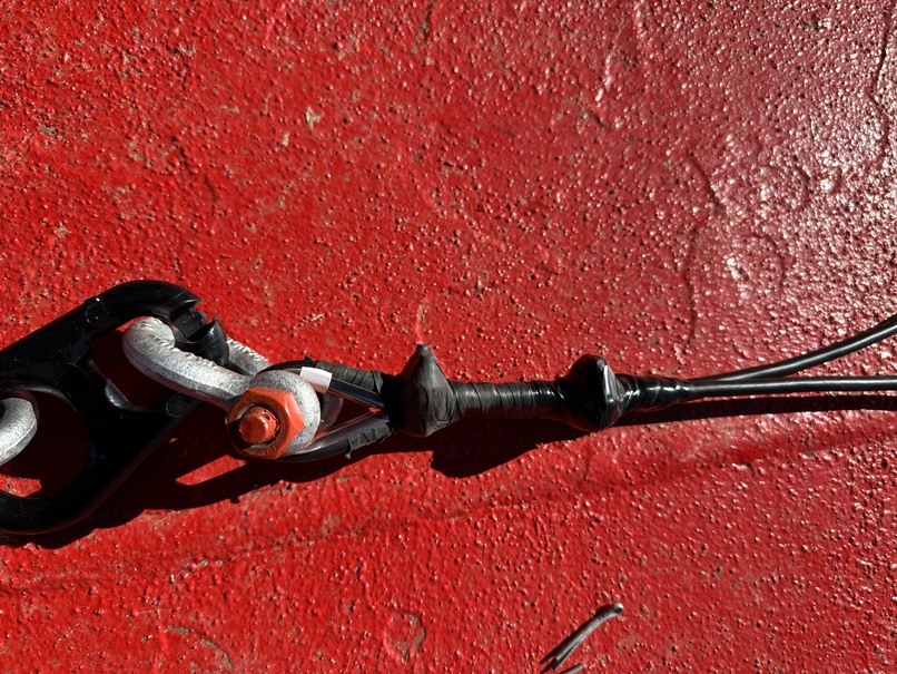
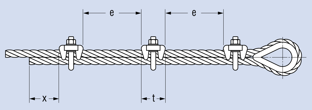
Below an illustration on how to terminate the wire properly (for more details check PDFs in docs wirelocks-1 and wirelocks-2). In our case the wire usually is Ø ≈ 6 mm (wire 3/16", jacket 1/4"). This requires M6 wirelocks, be aware of the orientation. According to the technical manuals 3 wirelocks are recommended, but for our purpose 2 are sufficient. According to the tables in the documentation the gaps are then e = 40 mm and x = 100 mm.
UM super-capacitors#
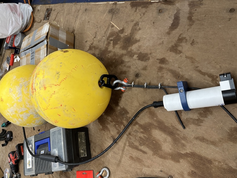
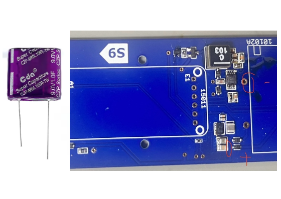
The super-capacitors on the ultimodems are in case there is a large start up power draw on the 12V output - more than the batteries can handle. They are connected as in the picture below.
Underwater cable#
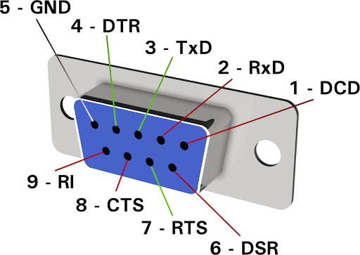
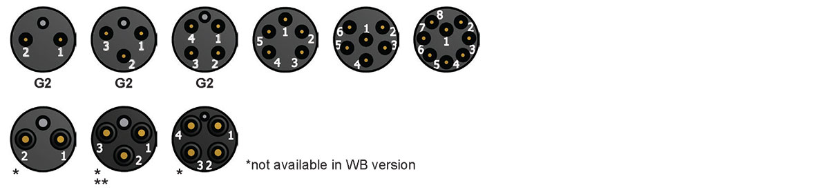
General pin layout of underwater contacts (male).
ISA500 to UM#
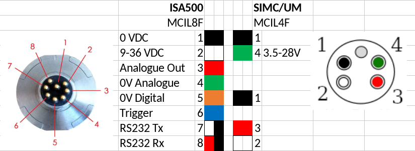
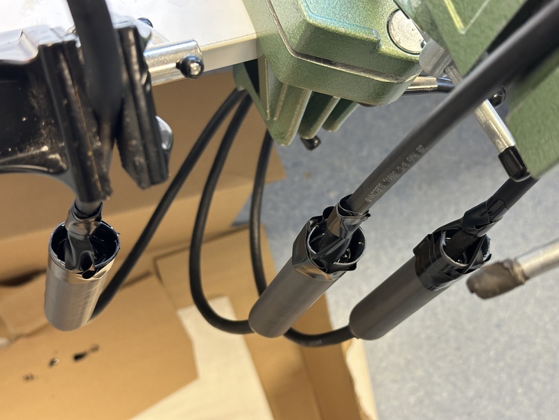
Dismantle both cables MCIL8F (ISA500) and MCIL4F (SIMC/UM). On the MCIL8F terminate 3, 4 and 6 with shrink tube. Solder together 1 and 5 and put some solder on all of the endings on both cables. In the end, slide 4 small shrink tubes on.
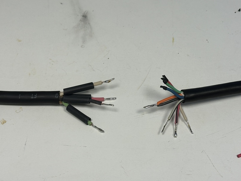
Connect the wires shown in the table above.
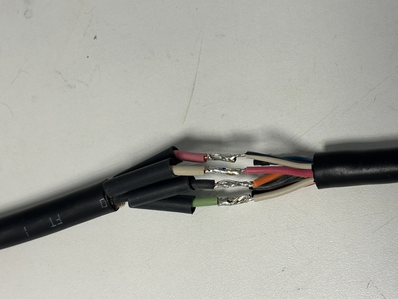
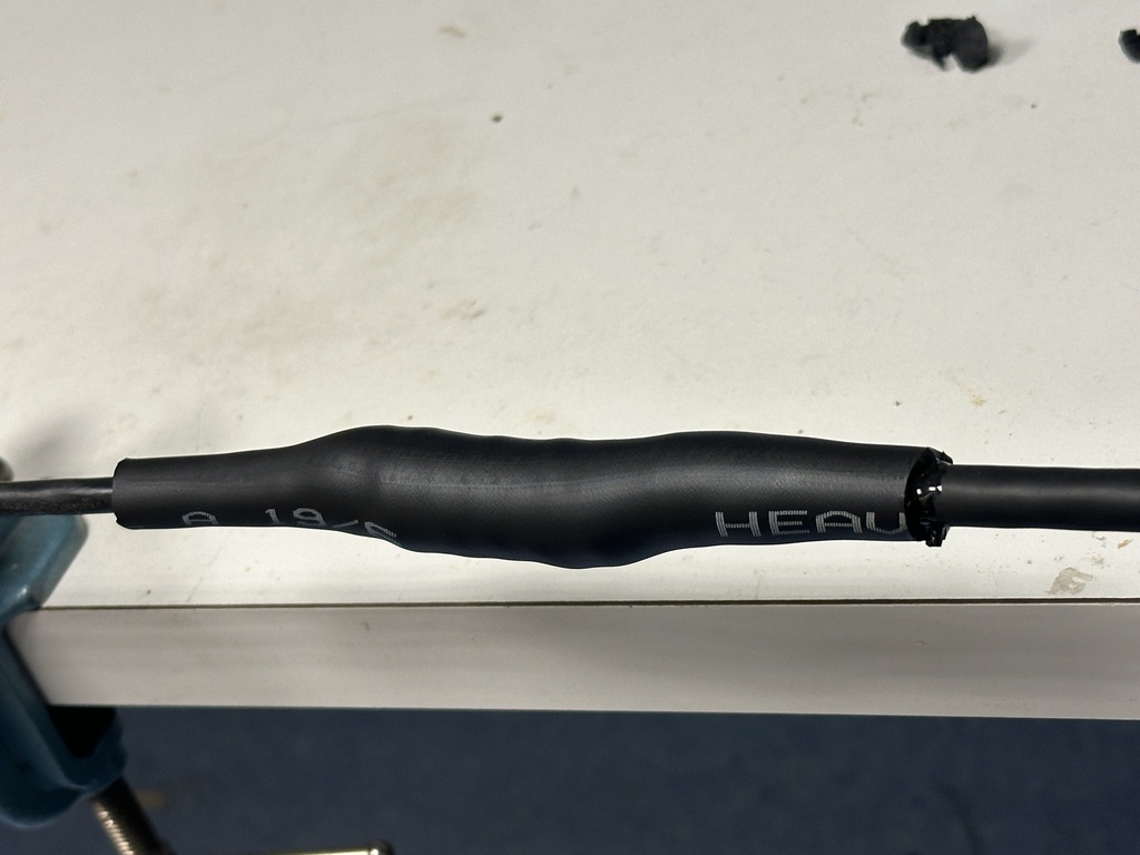
Shrink the tubes and prepare the big shrink tube (19/6mm).
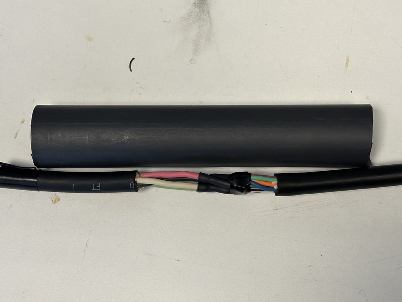
Use some sandpaper to roughen the mantle of the cable and clean with alcohol.
Shrink the tube only on one side.
Fix vertical and fill with cast resin (e.g. 3M Scotchcast). Fix with some tape to stay centered and leave over night. Shrink the final part when the resin has hardened.
Double weaklink#
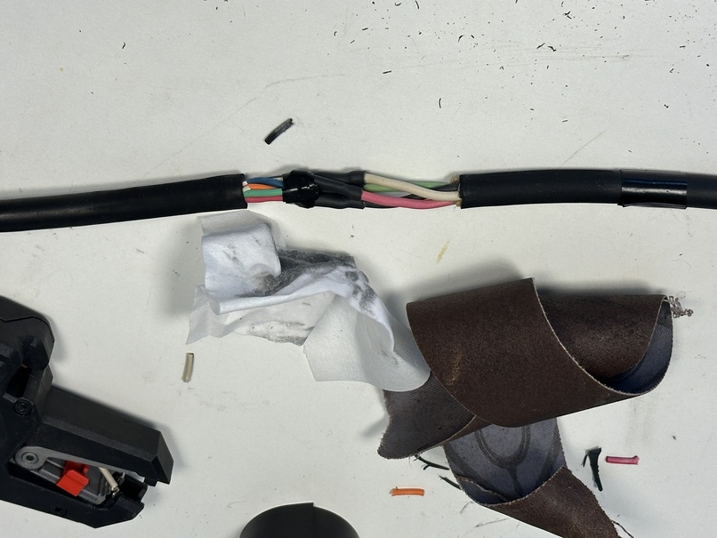
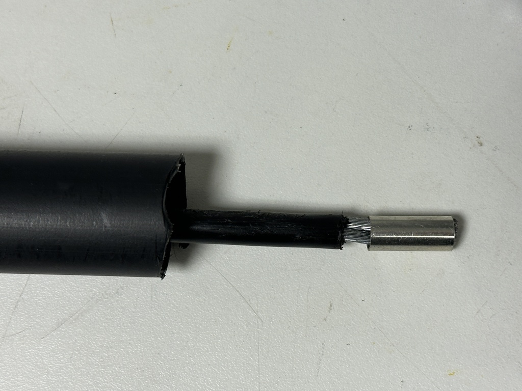
When adding another weaklink in the middle of the inductive wire, the signal needs to be forwarded without being strongly attached in case the weaklink breaks. Therefore an underwater plug is used and connected to the inductive wire as shown below via a «skjøtehylse» (joint sleeve 6-25 mm²).
Slide a long enough shrink tube with glue on the cable (6-19), strip the wire for some millimeter so that the metal ring of the joint sleeve fits on.
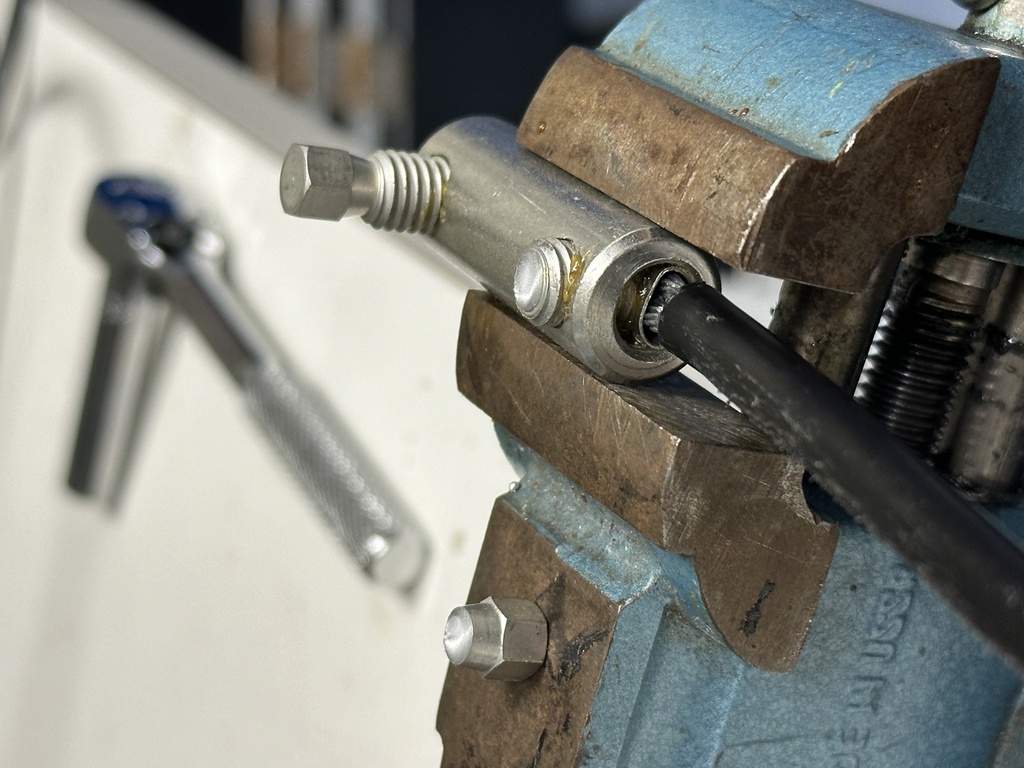
Place in outer joint sleeve and screw to press in the cable until the screw breaks.
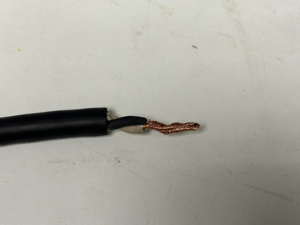
Strip enough on the underwater cable to fold the wire and make thick enough to fit into the joint sleeve.
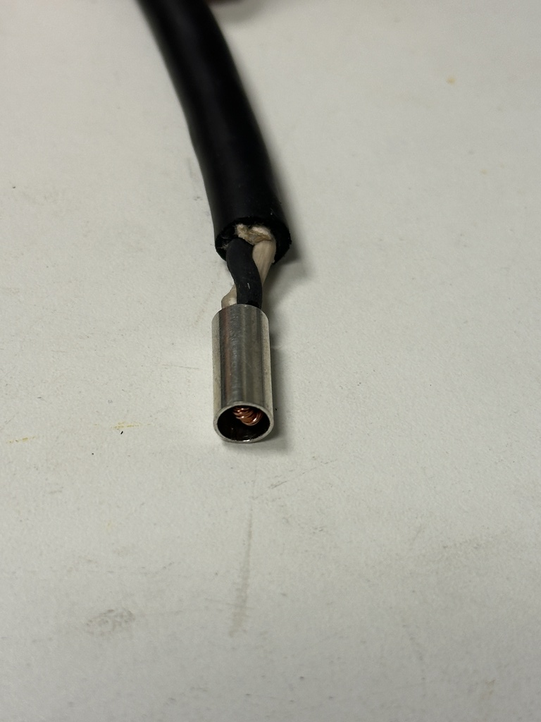
Also screw into the joint sleeve until the screw breaks, file down to remove edges and fill the gaps with rubber mass.
Cover with vulc/splicing tape.
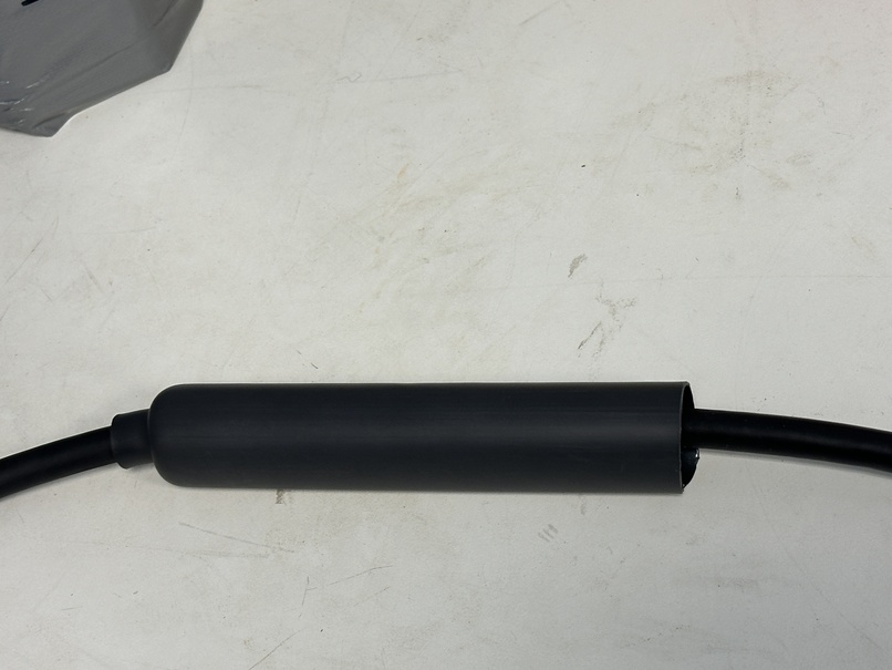
Melt on shrink tube.
Buoy prusik#
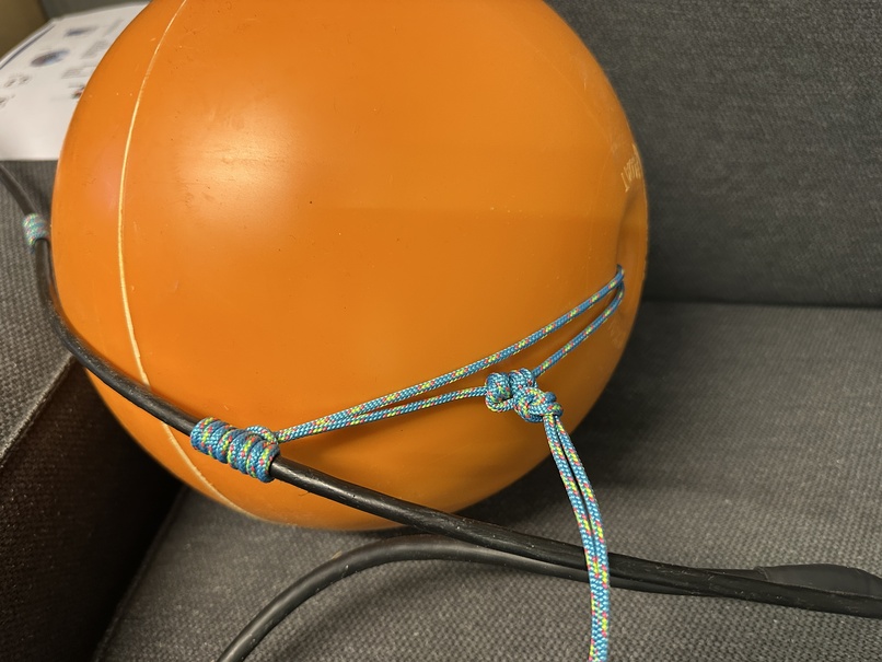
Around 200 mm of 3 mm rope is needed to fix trawl buoys to the wire with a prusik knot as shown in the picture below. These are for instance used below and above of an SBE37.
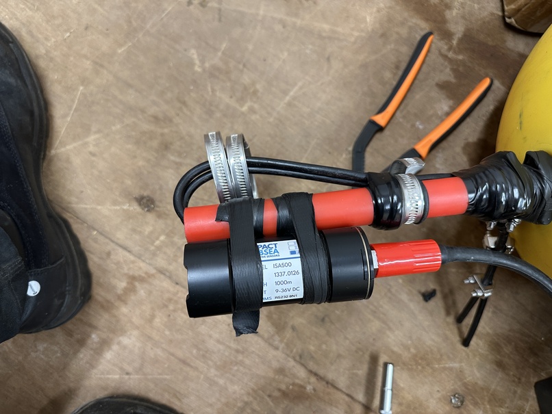
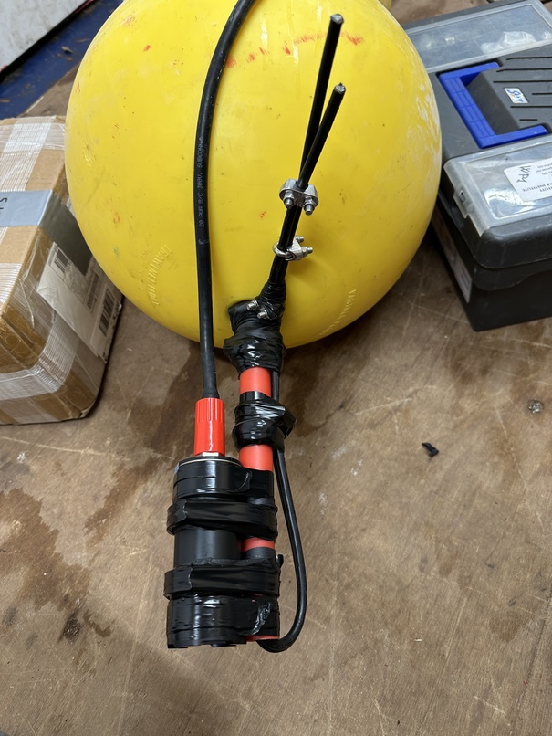
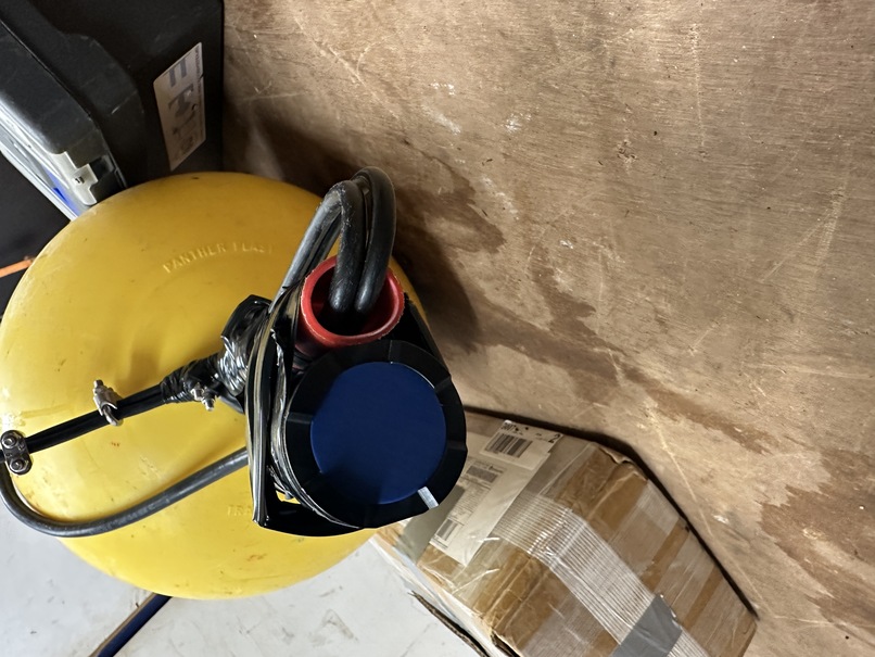
ISA500 buoy#
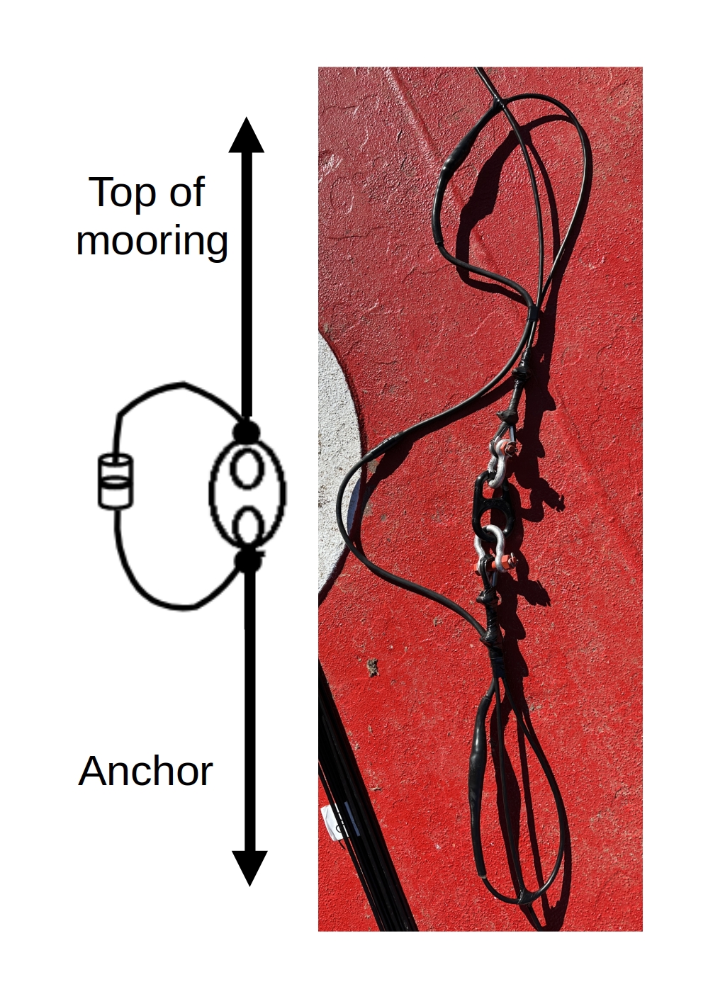
The sketch below shows the principal of the buoy system that is used to mount the ISA500. The idea is that the pole through the trawl buoys keeps the setup vertical due to its stiffness. The wire that goes through the pole is attached to the “breaking/weak” side of the weaklink below the buoys. This way, if the weaklink breaks the ISA500 is still attached via the subsea cable to the UM on the line below. The whole setup could then turn upside down and the trawl buoys can slide off the pole, leaving the ISA500 and pole behind hanging on the UM and the whole setup will sink down because of the lost buoyancy, keeping the instruments and only missing the buoys.
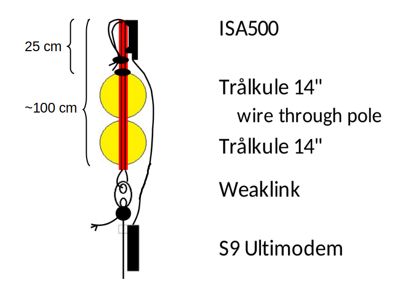
In order to build the setup first feed the cable through the weaklink and the red pole which has the trawl buoys on it. In this case the weaklink was halfed to reduce the break point from 600 lbs to 300 lbs.
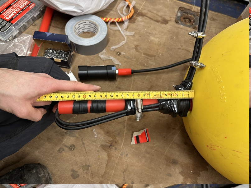
Next lock the cable on the upper side, two wire locks (instead of the 3 in the picture) should be enough. Use hose clamps to attach onto the red pole where some vulk tape is under for protection and anti glide on the red pole. The hose clamp closest to the poles is used as stopper for the trawl buoys that will press against when in water.
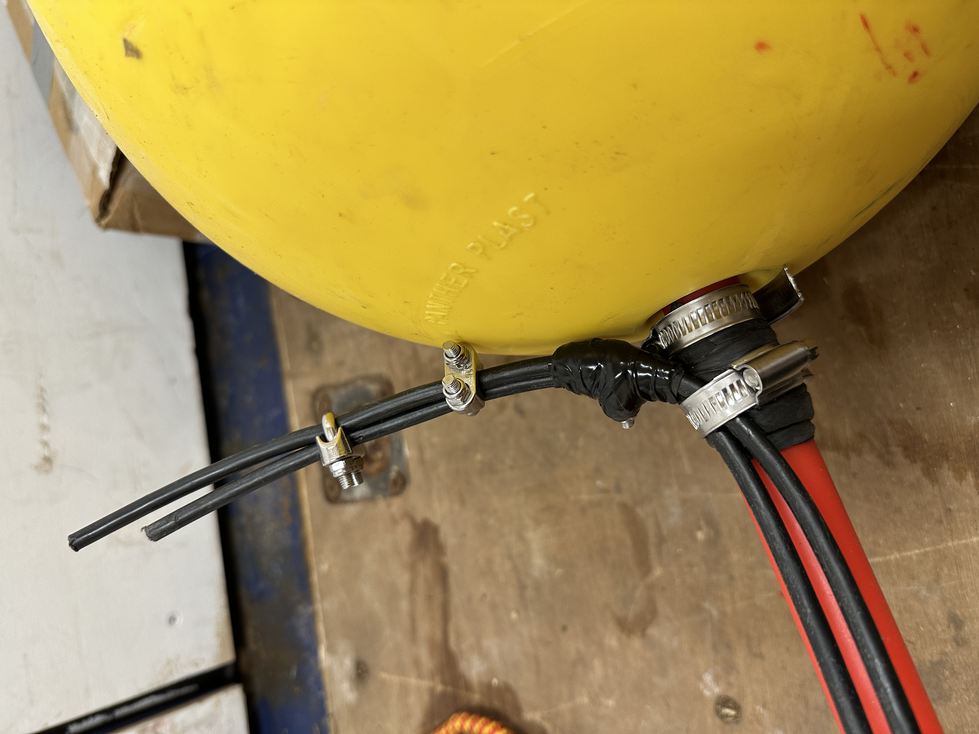
Cover hose clamps with some electric tape and add another hose clamp a few centimeter further up to get the cable closer to the red pole..
Add the ISA500 on the opposite side with the flat part of the housing pressing against the pole and the top aligned horizontally with the pole. Use vulc tape first, hose clamps on top and secure with electric tape in the end.
Connect weaklink and underwater cable to the wire and UM respectively.